|
Electronic Components Datasheet Search |
|
|
Electronic Components Datasheet Search |
|
MPM3686 Datasheet(PDF) 13 Page - Monolithic Power Systems |
|
|
|||||||||||||||||||||||||||||
MPM3686 Datasheet(HTML) 13 Page - Monolithic Power Systems |
|
|
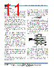
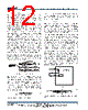
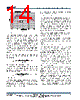
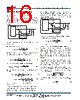
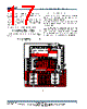
13 / 19 page  MPM3686 – 18V 20A STEP-DOWN POWER MODULE MPM3686 Rev. 1.02 www.MonolithicPower.com 13 10/13/2016 MPS Proprietary Information. Patent Protected. Unauthorized Photocopy and Duplication Prohibited. © 2016 MPS. All Rights Reserved. Table 1 shows the switching frequency with different common output voltages: Vo (V) fs(KHz) 1400 1.2 500 1.5 600 1.8 700 Table 1 If a switching frequency other than those listed in Table 1 is desired, an external frequency set resistor can be connected as shown in figure 5: Figure 5 The switching frequency can be estimated through equation (4) as follows: 6 SW FREQ IN DELAY IN OUT 10 F(kHz) 6.1 R (k ) V(V) T(ns) V(V) 0.4 V (V) (4) Where TDELAY is the comparator delay of about 5ns. Typically, the MPM3686 is set to 200kHz to 1MHz applications. Thanks to its monolithic structure, the MPM3686 is optimized to operate at high switching frequencies at high efficiency. High switching frequencies allow for physically smaller LC filter components to reduce the PCB footprint. Configuring the EN Control The power module turns on when EN goes high; conversely it turns off when EN goes low. Do not float the pin. For automatic start-up, pull the EN pin up to input voltage through a resistive voltage divider. Choose the values of the pull-up resistor (RUP from the IN pin to the EN pin) and the pull-down resistor (RDOWN from the EN pin to GND) to determine the automatic start-up voltage: UP DOWN IN START DOWN (R R ) V1.5 (V) R (5) For example, for RUP=100kΩ and RDOWN=51kΩ, the VIN-START is set at 4.44V. To reduce noise, add a 10nF ceramic capacitor from EN to GND. An internal zener diode on the EN pin clamps the EN pin voltage to prevent running away. The maximum pull up current (assuming the worst case 6V for the internal zener clamp) should be limited to 1mA or less. Therefore, when driving EN with an external logic signal, the driving voltage should be less than 6V. When connecting EN to IN through a pull-up resistor or a resistive voltage divider, select a resistance that ensures a maximum pull-up current of 1mA. If using a resistive voltage divider and VIN exceeds 6V, then the minimum resistance for the pull-up resistor RUP should meet: IN UP DOWN V6V 6V 1mA RR (6) With only RUP (the pull-down resistor, RDOWN, is not connected), then the VCC UVLO threshold determines VIN-START, so the minimum resistor value is: IN UP V6V R( ) 1mA (7) A typical pull-up resistor is 100kΩ. VCC Power Supply The MPM3686 has an internal VCC LDO to supply the power to the internal circuits and drives the power devices. This VCC LDO is derived from the input supply. To ensure proper operation, the minimum input voltage should be 4.5V. An external 5V VCC bias can disable the internal LDO. In this case, Vin can be as low as 2.5V. The efficiency can be higher with external 5V VCC bias. Figure 6 shows the comparison. |
|
|
Link URL |
| Does ALLDATASHEET help your business so far? [ DONATE ] |
About Alldatasheet | Advertisement | Contact us | Privacy Policy | Link to Datasheet | Link Exchange | Manufacturer List All Rights Reserved©Alldatasheet.com |
| Russian : Alldatasheetru.com | Korean : Alldatasheet.co.kr | Spanish : Alldatasheet.es | French : Alldatasheet.fr | Italian : Alldatasheetit.com Portuguese : Alldatasheetpt.com | Polish : Alldatasheet.pl | Vietnamese : Alldatasheet.vn Indian : Alldatasheet.in | Mexican : Alldatasheet.com.mx | British : Alldatasheet.co.uk | New Zealand : Alldatasheet.co.nz |
|
Family Site : ic2ic.com |
icmetro.com |
 British ▼
 English
 Chinese
 German
 Japanese
 Russian
 Korean
 Spanish
 French
 Italian
 Portuguese
 Polish
 Vietnamese
 Indian
 Mexican
 British
 New Zealand