|
Electronic Components Datasheet Search |
|
|
Electronic Components Datasheet Search |
|
MPM3686 Datasheet(PDF) 11 Page - Monolithic Power Systems |
|
|
|||||||||||||||||||||||||||||
MPM3686 Datasheet(HTML) 11 Page - Monolithic Power Systems |
|
|
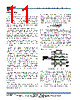
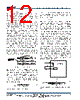
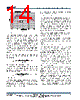
11 / 19 page  MPM3686 – 18V 20A STEP-DOWN POWER MODULE MPM3686 Rev. 1.02 www.MonolithicPower.com 11 10/13/2016 MPS Proprietary Information. Patent Protected. Unauthorized Photocopy and Duplication Prohibited. © 2016 MPS. All Rights Reserved. OPERATION Power Module Operation The MPM3686 is a high performance single output synchronous switching mode DC-to-DC power supply. It can deliver 20A continuous output current. The MPM3686 can provide an output voltage from 0.65V to 5V over a 4.5V to 18V (or 2.5V to 18V with 5V external VCC bias) wide input voltage range. The MPM3686 is a complete power solution. It integrates a constant-on-time (COT) control DC- to-DC regulator, power devices, an inductor, input/output capacitors and some other supporting resistors and small capacitors. It only needs as few as one external resistor and one external small capacitor to operate. The MPM3686 is controlled by both the VCC voltage and the EN signal. It can only be turned on when both voltages are higher than the thresholds. The switching frequency is determined by a frequency set resistor. The default switching frequency with the integrated resistor is shown in table 1. The default switching frequency increases with the output voltage. The switching frequency can also be programmed externally in the range of 200KHz to 1000KHz. The details can be found in the section of “SWITCHING FREQUENCY SETTING” on Page 12. The MPM3686 utilizes constant-on-time control. It has sufficient stability margin with simple loop compensation. And it provides very good transient response with a wide range of output capacitors, even with all ceramic output capacitors. The MPM3686 has a variable soft start timer to smooth-out the output voltage during start-up. The default (with SS pin floating) soft start timer is about 3ms. The soft-start time can be extended by adding a capacitor between SS pin and AGND pin. PWM Operation The MPM3686 uses Constant-on-time (COT) control to provide a fast transient response and ease loop stabilization. At the beginning of each cycle, the high-side MOSFET (HS-FET) turns ON when the feedback voltage (VFB) drops below the reference voltage (VREF), which indicates an insufficient output voltage. The input voltage and the frequency-set resistor determine the ON period as follows: FREQ ON IN 6.1 R (k ) T(ns) V(V) 0.4 (1) After the ON period elapses, the HS-FET turns off. It turns ON again when VFB drops below VREF. By repeating this operation, the converter regulates the output voltage to the desired level. The integrated low-side MOSFET (LS-FET) turns on when the HS-FET is OFF to minimize the conduction loss. There is a dead short (or shoot- through) between input and GND if both HS-FET and LS-FET turn on at the same time. A dead- time (DT) internally generated between HS-FET OFF and LS-FETON, or LS-FET OFF and HS- FET ON avoids shoot-through. Heavy-Load Operation Figure 2—Heavy Load Operation When the output current is high and the inductor current is always above zero amps, it is called continuous-conduction-mode (CCM). Figure 2 shows the CCM operation. When VFB is below VREF, HS-FET turns on for a fixed interval determined by the one-shot on-timer as per equation 1. When the HS-FET turns off, the LS- FET turns on until the next period. In CCM operation, the switching frequency is fairly constant and is also called PWM mode. |
|
|
Link URL |
| Does ALLDATASHEET help your business so far? [ DONATE ] |
About Alldatasheet | Advertisement | Contact us | Privacy Policy | Link to Datasheet | Link Exchange | Manufacturer List All Rights Reserved©Alldatasheet.com |
| Russian : Alldatasheetru.com | Korean : Alldatasheet.co.kr | Spanish : Alldatasheet.es | French : Alldatasheet.fr | Italian : Alldatasheetit.com Portuguese : Alldatasheetpt.com | Polish : Alldatasheet.pl | Vietnamese : Alldatasheet.vn Indian : Alldatasheet.in | Mexican : Alldatasheet.com.mx | British : Alldatasheet.co.uk | New Zealand : Alldatasheet.co.nz |
|
Family Site : ic2ic.com |
icmetro.com |
 British ▼
 English
 Chinese
 German
 Japanese
 Russian
 Korean
 Spanish
 French
 Italian
 Portuguese
 Polish
 Vietnamese
 Indian
 Mexican
 British
 New Zealand