|
Electronic Components Datasheet Search |
|
|
Electronic Components Datasheet Search |
|
AT89C5132-ROTIL Datasheet(PDF) 148 Page - ATMEL Corporation |
|
|
|||||||||||||||||||||||||||||
AT89C5132-ROTIL Datasheet(HTML) 148 Page - ATMEL Corporation |
|
|
148 / 181 page 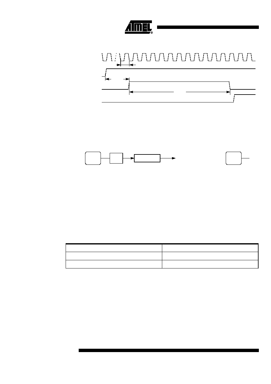 148 4173D–USB–02/06 AT89C5132 Figure 21-2. Timing Diagram 21.1.1 Clock Generator The ADC clock is generated by division of the peripheral clock (see details in Section “X2 Fea- ture”, page 12). The division factor is then given by ADCP4:0 bits in ADCLK register. Figure 21- 3 shows the ADC clock generator and its calculation formula (1). Figure 21-3. ADC Clock Generator and Symbol Caution: Note: 1. In all cases, the ADC clock frequency may be higher than the maximum FADCLK parameter reported in the Section “Analog to Digital Converter”, page 201. 2. The ADCD value of 0 is equivalent to an ADCD value of 32. 21.1.2 Channel Selection The channel on which conversion is performed is selected by the ADCS bit in ADCON register according to Table 30. Table 30. ADC Channel Selection 21.1.3 Conversion Precision The 10-bit precision conversion is achieved by stopping the CPU core activity during conversion for limiting the digital noise induced by the core. This mode called the Pseudo-Idle mode(1),(2) is enabled by setting the ADIDL bit in ADCON register(3). Thus, when conversion is launched (see Section "Conversion Launching", page 149), the CPU core is stopped until the end of the con- ADEN ADSST ADEOC T SETUP T CONV CLK T ADCLK ADCD4:0 ADCLK ADC Clock ADCclk PERclk 2 ADCD ⋅ ------------------------- = ADC Clock Symbol ADC CLOCK PER CLOCK ÷ 2 ADCS Channel 0AIN1 1AIN0 |
|
Link URL |
| Does ALLDATASHEET help your business so far? [ DONATE ] |
About Alldatasheet | Advertisement | Contact us | Privacy Policy | Link to Datasheet | Link Exchange | Manufacturer List All Rights Reserved©Alldatasheet.com |
| Russian : Alldatasheetru.com | Korean : Alldatasheet.co.kr | Spanish : Alldatasheet.es | French : Alldatasheet.fr | Italian : Alldatasheetit.com Portuguese : Alldatasheetpt.com | Polish : Alldatasheet.pl | Vietnamese : Alldatasheet.vn Indian : Alldatasheet.in | Mexican : Alldatasheet.com.mx | British : Alldatasheet.co.uk | New Zealand : Alldatasheet.co.nz |
|
Family Site : ic2ic.com |
icmetro.com |
 British ▼
 English
 Chinese
 German
 Japanese
 Russian
 Korean
 Spanish
 French
 Italian
 Portuguese
 Polish
 Vietnamese
 Indian
 Mexican
 British
 New Zealand