|
Electronic Components Datasheet Search |
|
|
Electronic Components Datasheet Search |
|
AT89C5132-ROTIL Datasheet(PDF) 150 Page - ATMEL Corporation |
|
|
|||||||||||||||||||||||||||||
AT89C5132-ROTIL Datasheet(HTML) 150 Page - ATMEL Corporation |
|
|
150 / 181 page 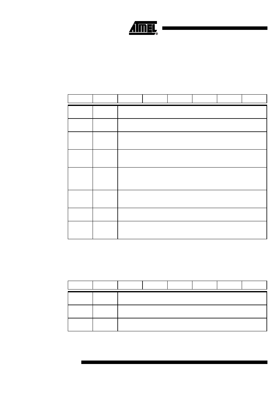 150 4173D–USB–02/06 AT89C5132 enabled by setting EADC bit in IEN1 register. This flag is set by hardware and must be reset by software. 21.2 Registers Table 31. ADCON Register ADCON (S:F3h) – ADC Control Register Reset Value = 0000 0000b Table 32. ADCLK Register ADCLK (S:F2h) – ADC Clock Divider Register Reset Value = 0000 0000b 765 4321 0 - ADIDL ADEN ADEOC ADSST - - ADCS Bit Number Bit Mnemonic Description 7- Reserved The value read from this bit is always 0. Do not set this bit. 6 ADIDL ADC Pseudo-Idle Mode Set to suspend the CPU core activity (pseudo-idle mode) during conversion. Clear by hardware at the end of conversion. 5ADEN ADC Enable Bit Set to enable the A to D converter. Clear to disable the A to D converter and put it in low power stand by mode. 4ADEOC End Of Conversion Flag Set by hardware when ADC result is ready to be read. This flag can generate an interrupt. Must be cleared by software. 3 ADSST Start and Status Bit Set to start an A to D conversion on the selected channel. Cleared by hardware at the end of conversion. 2 - 1 - Reserved The value read from these bits is always 0. Do not set these bits. 0 ADCS Channel Selection Bit Set to select channel 0 for conversion. Clear to select channel 1 for conversion. 765 4321 0 - - - ADCD4 ADCD3 ADCD2 ADCD1 ADCD0 Bit Number Bit Mnemonic Description 7 - 5 - Reserved The value read from these bits is always 0. Do not set these bits. 4 - 0 ADCD4:0 ADC Clock Divider 5-bit divider for ADC clock generation. |
|
Link URL |
| Does ALLDATASHEET help your business so far? [ DONATE ] |
About Alldatasheet | Advertisement | Contact us | Privacy Policy | Link to Datasheet | Link Exchange | Manufacturer List All Rights Reserved©Alldatasheet.com |
| Russian : Alldatasheetru.com | Korean : Alldatasheet.co.kr | Spanish : Alldatasheet.es | French : Alldatasheet.fr | Italian : Alldatasheetit.com Portuguese : Alldatasheetpt.com | Polish : Alldatasheet.pl | Vietnamese : Alldatasheet.vn Indian : Alldatasheet.in | Mexican : Alldatasheet.com.mx | British : Alldatasheet.co.uk | New Zealand : Alldatasheet.co.nz |
|
Family Site : ic2ic.com |
icmetro.com |
 British ▼
 English
 Chinese
 German
 Japanese
 Russian
 Korean
 Spanish
 French
 Italian
 Portuguese
 Polish
 Vietnamese
 Indian
 Mexican
 British
 New Zealand