 |
Electronic Components Datasheet Search |
|
|
Electronic Components Datasheet Search |
|
AT89C5132-ROTIL Datasheet(PDF) 149 Page - ATMEL Corporation |
|
|
|||||||||||||||||||||||||||||
AT89C5132-ROTIL Datasheet(HTML) 149 Page - ATMEL Corporation |
|
|
149 / 182 page 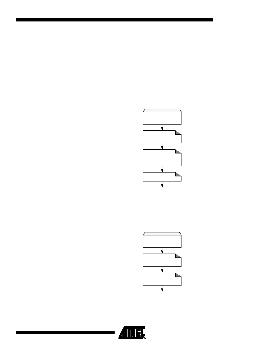 149 4173E–USB–09/07 AT89C5132 version (see Section "End Of Conversion", page 149). This bit is cleared by hardware at the end of the conversion. Notes: 1. Only the CPU activity is frozen, peripherals are not affected by the Pseudo-Idle mode. 2. If some interrupts occur during the Pseudo-Idle mode, they will be delayed and processed, according to their priority after the end of the conversion. 3. Concurrently with ADSST bit. 21.1.4 Configuration The ADC configuration consists in programming the ADC clock as detailed in the Section "Clock Generator", page 148. The ADC is enabled using the ADEN bit in ADCON register. As shown in Figure 93, user must wait the setup time (TSETUP) before launching any conversion. Figure 21-4. ADC Configuration Flow 21.1.5 Conversion Launching The conversion is launched by setting the ADSST bit in ADCON register, this bit remains set during the conversion. As soon as the conversion is started, it takes 11 clock periods (TCONV) before the data is available in ADDH and ADDL registers. Figure 21-5. ADC Conversion Launching Flow 21.1.6 End Of Conversion The end of conversion is signalled by the ADEOC flag in ADCON register becoming set or by the ADSST bit in ADCON register becoming cleared. ADEOC flag can generate an interrupt if ADC Configuration Enable ADC ADIDL = x ADEN = 1 Wait Setup Time Program ADC Clock ADCD4:0 = xxxxxb ADC Conversion Start Select Channel ADCS = 0-1 Start Conversion ADSST = 1 |
|
Link URL |
| Does ALLDATASHEET help your business so far? [ DONATE ] |
About Alldatasheet | Advertisement | Contact us | Privacy Policy | Link to Datasheet | Link Exchange | Manufacturer List All Rights Reserved©Alldatasheet.com |
| Russian : Alldatasheetru.com | Korean : Alldatasheet.co.kr | Spanish : Alldatasheet.es | French : Alldatasheet.fr | Italian : Alldatasheetit.com Portuguese : Alldatasheetpt.com | Polish : Alldatasheet.pl | Vietnamese : Alldatasheet.vn Indian : Alldatasheet.in | Mexican : Alldatasheet.com.mx | British : Alldatasheet.co.uk | New Zealand : Alldatasheet.co.nz |
|
Family Site : ic2ic.com |
icmetro.com |
 British ▼
 English
 Chinese
 German
 Japanese
 Russian
 Korean
 Spanish
 French
 Italian
 Portuguese
 Polish
 Vietnamese
 Indian
 Mexican
 British
 New Zealand


