|
Electronic Components Datasheet Search |
|
|
Electronic Components Datasheet Search |
|
T89C5115-RATIM Datasheet(PDF) 17 Page - ATMEL Corporation |
|
|
|||||||||||||||||||||||||||||
T89C5115-RATIM Datasheet(HTML) 17 Page - ATMEL Corporation |
|
|
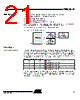
17 / 105 page 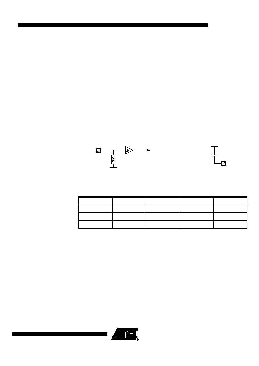 17 T89C5115 4128A–8051–04/02 Power Management Introduction Two power reduction modes are implemented in the T89C5115: the Idle mode and the Power-down mode. These modes are detailed in the following sections. In addition to these power reduction modes, the clocks of the core and peripherals can be dynamically divided by 2 using the X2 mode detailed in Section “Clock”. Reset A reset is required after applying power at turn-on. To achieve a valid reset, the reset signal must be maintained for at least 2 machine cycles (24 oscillator clock periods) while the oscillator is running and stabilized and VCC established within the specified operating ranges. A device reset initializes the T89C5115 and vectors the CPU to address 0000h. RST input has a pull-down resistor allowing power-on reset by simply connecting an external capacitor to V DD as shown in Figure 5. Resistor value and input characteristics are discussed in the Section “DC Characteristics” of the T89C5115 datasheet. The status of the Port pins during reset is detailed in Table 13. Figure 5. Reset Circuitry and Power-On Reset Table 13. Pin Conditions in Special Operating Modes Reset Recommendation to Prevent Flash Corruption A bad reset sequence will lead to bad microcontroller initialization and system registers like SFR’s, Program Counter, etc. will not be correctly initialized. A bad initialization may lead to unpredictable behaviour of the C51 microcontroller. An example of this situation may occur in an instance where the bit ENBOOT in AUXR1 register is initialized from the hardware bit BLJB upon reset. Since this bit allows map- ping of the bootloader in the code area, a reset failure can be critical. If one wants the ENBOOT cleared inorder to unmap the boot from the code area (yet due to a bad reset) the bit ENBOOT in SFR’s may be set. If the value of Program Counter is accidently in the range of the boot memory addresses then a flash access (write or erase) may corrupt the Flash on-chip memory . It is recommended to use an external reset circuitry featuring power supply monitoring to prevent system malfunction during periods of insufficient power supply voltage(power supply failure, power supply switched off). Mode Port 1 Port 2 Port 3 Port 4 Reset High High High High Idle Data Data Data Data Power-down DataDataDataData RST VSS To CPU core and peripherals RST VDD + b. Power-on Reset a. RST input circuitry |
|
Link URL |
| Does ALLDATASHEET help your business so far? [ DONATE ] |
About Alldatasheet | Advertisement | Contact us | Privacy Policy | Link to Datasheet | Link Exchange | Manufacturer List All Rights Reserved©Alldatasheet.com |
| Russian : Alldatasheetru.com | Korean : Alldatasheet.co.kr | Spanish : Alldatasheet.es | French : Alldatasheet.fr | Italian : Alldatasheetit.com Portuguese : Alldatasheetpt.com | Polish : Alldatasheet.pl | Vietnamese : Alldatasheet.vn Indian : Alldatasheet.in | Mexican : Alldatasheet.com.mx | British : Alldatasheet.co.uk | New Zealand : Alldatasheet.co.nz |
|
Family Site : ic2ic.com |
icmetro.com |
 British ▼
 English
 Chinese
 German
 Japanese
 Russian
 Korean
 Spanish
 French
 Italian
 Portuguese
 Polish
 Vietnamese
 Indian
 Mexican
 British
 New Zealand