 |
Electronic Components Datasheet Search |
|
|
Electronic Components Datasheet Search |
|
The question interval is too short.
Please try again in a few seconds.

Hello, Please ask a question about Z87200 Datasheet
# Example questions:
➢ What is the typical operational supply current (i dd) of the z87200 and what factors influence this value?
➢ What is the minimum time required for the rxtest 7-0 outputs to become active after /oen goes low?
➢ Referring to the ac characteristics - receiver section, describe the relationship between rxifclk, rxsplpls, and the /rxdrdy signal.
| Part No. | Z87200 |
| Manufacturer | ZILOG |
| Size | 449 Kbytes |
| Pages | 54 pages |
| Description | Spread-Spectrum Transceiver |


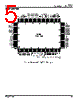

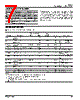
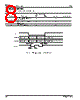
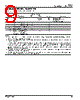


1. General Information
️· Device: Zilog Z87200 Spread-Spectrum Transceiver
️· Purpose: A device for wireless communication, likely designed for a specific frequency range (indicated by various frequency values - see below). It's intended to be a component in a larger system.
️· Target Application: Likely a communication system requiring spread spectrum technology (for robustness against interference and security). It is microprocessor-compatible.
️· Operating Voltage: 5.0V ± 5% (This is a common voltage, but important to verify)
️· Operating Temperature: 0°C to +70°C
2. Features
️· Spread Spectrum: Core functionality for robustness and security. It allows for resistance to noise and jamming.
️· Microprocessor Compatible: Designed to easily interface with microprocessors.
️· Programmable: Key features, like chip rate, are programmable via addressable registers (bit 5-0 of address 41H for TX, bit 5-0 of address 02H for RX).
️· QPSK (Quadrature Phase-Shift Keying) Modulation: A modulation scheme, allowing for transmitting two bits of data per symbol. This doubles the data rate compared to simpler modulation techniques.
️· Flexible Chip Rate Control: Programmable chip rate allows for adapting to different data rates.
️· Testability: Test registers (RXTEST 7-0) allow for diagnostic testing.
3. Electrical Characteristics
️· Supply Current (I DD): Crucial for power budget calculations. The document states this depends on configuration, but gives some ranges. The documentation says the typical operational supply current can be approximated with a formula.
️· Input/Output Voltages: Standard logic voltage levels (e.g., VIH = 0.7V, VIL = 0.2V).
️· Output Drive Capability: Limited current drive (OS = 20mA to 130mA). Important for external circuitry design.
️· Input Capacitance: Impacting frequency response and signal integrity.
️· Output Capacitance: Affects circuit loading and speed.
️· Short Circuit Current: Important to consider for protection.
4. Timing Characteristics (Key Area)
This section defines the timing relationships between various signals. Here's a summarized breakdown. These define how quickly things must happen for proper operation.
️· RXIFCLK: Main clock frequency (specified as 45.056 MHz and 20.0 MHz). This determines the data rate.
️· TXIFCLK: Transmitter clock frequency
️· TXCHPPLS: Transmitter chip clock. Defines the chip rate.
️· RXSPLPLS: Receiver Symbol clock.
️· RXSYMPLS: Receiver Symbol clock
️· /RXDRDY: Receiver Data Ready signal. Indicates when received data is valid.
️· RXOUT, RXIOUT, RXQOUT: Receiver data outputs.
️· TXBITPLS: Transmitter bit pulse.
️· TXTRKPLS: Transmitter track pulse
️· TXACQPLS: Transmitter Acquisition pulse
️· Testability /OEN to RXTEST Timing: Defines the timing for accessing the test registers via /OEN
Specific Timing Notes:
️· Setup and Hold Times: (tSU, tHD). Crucial for reliable data transfer. These define the required timing relative to RXIFCLK.
️· Propagation Delays: (t CR, t CD). Propagation delays are inherent in circuits - the documentation specifies some values.
️· /OEN to RXTEST Timing: (tD1, tD2). The test signals must be stable for the given amount of time.
Important Notes and Takeaways:
️· Frequency Dependence: The datasheet refers to frequencies (45.056 MHz, 20.0 MHz). Verify the intended frequency range for your application.
️· Programmability: The ability to program the chip rate and other parameters offers flexibility but requires careful configuration.
️· Timing is Critical: The timing characteristics are vital for reliable operation. Pay very close attention to setup and hold times, and propagation delays. Simulating or carefully designing the surrounding circuitry is essential.
️· Datasheet is dense: The datasheet is a dense technical document. It requires a good understanding of digital electronics and wireless communication principles to interpret correctly.
1. General Information
️· Device: Zilog Z87200 Spread-Spectrum Transceiver
️· Purpose: A device for wireless communication, likely designed for a specific frequency range (indicated by various frequency values - see below). It's intended to be a component in a larger system.
️· Target Application: Likely a communication system requiring spread spectrum technology (for robustness against interference and security). It is microprocessor-compatible.
️· Operating Voltage: 5.0V ± 5% (This is a common voltage, but important to verify)
️· Operating Temperature: 0°C to +70°C
2. Features
️· Spread Spectrum: Core functionality for robustness and security. It allows for resistance to noise and jamming.
️· Microprocessor Compatible: Designed to easily interface with microprocessors.
️· Programmable: Key features, like chip rate, are programmable via addressable registers (bit 5-0 of address 41H for TX, bit 5-0 of address 02H for RX).
️· QPSK (Quadrature Phase-Shift Keying) Modulation: A modulation scheme, allowing for transmitting two bits of data per symbol. This doubles the data rate compared to simpler modulation techniques.
️· Flexible Chip Rate Control: Programmable chip rate allows for adapting to different data rates.
️· Testability: Test registers (RXTEST 7-0) allow for diagnostic testing.
3. Electrical Characteristics
️· Supply Current (I DD): Crucial for power budget calculations. The document states this depends on configuration, but gives some ranges. The documentation says the typical operational supply current can be approximated with a formula.
️· Input/Output Voltages: Standard logic voltage levels (e.g., VIH = 0.7V, VIL = 0.2V).
️· Output Drive Capability: Limited current drive (OS = 20mA to 130mA). Important for external circuitry design.
️· Input Capacitance: Impacting frequency response and signal integrity.
️· Output Capacitance: Affects circuit loading and speed.
️· Short Circuit Current: Important to consider for protection.
4. Timing Characteristics (Key Area)
This section defines the timing relationships between various signals. Here's a summarized breakdown. These define how quickly things must happen for proper operation.
️· RXIFCLK: Main clock frequency (specified as 45.056 MHz and 20.0 MHz). This determines the data rate.
️· TXIFCLK: Transmitter clock frequency
️· TXCHPPLS: Transmitter chip clock. Defines the chip rate.
️· RXSPLPLS: Receiver Symbol clock.
️· RXSYMPLS: Receiver Symbol clock
️· /RXDRDY: Receiver Data Ready signal. Indicates when received data is valid.
️· RXOUT, RXIOUT, RXQOUT: Receiver data outputs.
️· TXBITPLS: Transmitter bit pulse.
️· TXTRKPLS: Transmitter track pulse
️· TXACQPLS: Transmitter Acquisition pulse
️· Testability /OEN to RXTEST Timing: Defines the timing for accessing the test registers via /OEN
Specific Timing Notes:
️· Setup and Hold Times: (tSU, tHD). Crucial for reliable data transfer. These define the required timing relative to RXIFCLK.
️· Propagation Delays: (t CR, t CD). Propagation delays are inherent in circuits - the documentation specifies some values.
️· /OEN to RXTEST Timing: (tD1, tD2). The test signals must be stable for the given amount of time.
Important Notes and Takeaways:
️· Frequency Dependence: The datasheet refers to frequencies (45.056 MHz, 20.0 MHz). Verify the intended frequency range for your application.
️· Programmability: The ability to program the chip rate and other parameters offers flexibility but requires careful configuration.
️· Timing is Critical: The timing characteristics are vital for reliable operation. Pay very close attention to setup and hold times, and propagation delays. Simulating or carefully designing the surrounding circuitry is essential.
️· Datasheet is dense: The datasheet is a dense technical document. It requires a good understanding of digital electronics and wireless communication principles to interpret correctly.
| Part No. | Z87200 |
| Manufacturer | ZILOG |
| Size | 449 Kbytes |
| Pages | 54 pages |
| Description | Spread-Spectrum Transceiver |
| Does ALLDATASHEET help your business so far? [ DONATE ] |
About Alldatasheet | Advertisement | Contact us | Privacy Policy | Link to Datasheet | Link Exchange | Manufacturer List All Rights Reserved©Alldatasheet.com |
| Russian : Alldatasheetru.com | Korean : Alldatasheet.co.kr | Spanish : Alldatasheet.es | French : Alldatasheet.fr | Italian : Alldatasheetit.com Portuguese : Alldatasheetpt.com | Polish : Alldatasheet.pl | Vietnamese : Alldatasheet.vn Indian : Alldatasheet.in | Mexican : Alldatasheet.com.mx | British : Alldatasheet.co.uk | New Zealand : Alldatasheet.co.nz |
|
Family Site : ic2ic.com |
icmetro.com |
 British ▼
  English
 Chinese
 German
 Japanese
 Russian
 Korean
 Spanish
 French
 Italian
 Portuguese
 Polish
 Vietnamese
 Indian
 Mexican
 New Zealand