|
Electronic Components Datasheet Search |
|
|
Electronic Components Datasheet Search |
|
AT89C51ID2-RDTIM Datasheet(PDF) 23 Page - ATMEL Corporation |
|
|
|||||||||||||||||||||||||||||
AT89C51ID2-RDTIM Datasheet(HTML) 23 Page - ATMEL Corporation |
|
|
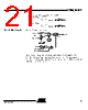
23 / 159 page  23 AT89C51ID2 4289A–8051–09/03 Figure 5. Mode Switching Waveforms The X2 bit in the CKCON0 register (see Table 20) allows a switch from 12 clock periods per instruction to 6 clock periods and vice versa. At reset, the speed is set according to X2 bit of Hardware Security Byte (HSB). By default, Standard mode is active. Setting the X2 bit activates the X2 feature (X2 mode). The T0X2, T1X2, T2X2, UartX2, PcaX2, and WdX2 bits in the CKCON0 register (See Table 20.) and SPIX2 bit in the CKCON1 register (see Table 21) allows a switch from standard peripheral speed (12 clock periods per peripheral clock cycle) to fast periph- eral speed (6 clock periods per peripheral clock cycle). These bits are active only in X2 mode. XTAL1:2 XTAL1 CPU clock X2 bit X2 Mode STD Mode STD Mode FOSC |
|
Link URL |
| Does ALLDATASHEET help your business so far? [ DONATE ] |
About Alldatasheet | Advertisement | Contact us | Privacy Policy | Link to Datasheet | Link Exchange | Manufacturer List All Rights Reserved©Alldatasheet.com |
| Russian : Alldatasheetru.com | Korean : Alldatasheet.co.kr | Spanish : Alldatasheet.es | French : Alldatasheet.fr | Italian : Alldatasheetit.com Portuguese : Alldatasheetpt.com | Polish : Alldatasheet.pl | Vietnamese : Alldatasheet.vn Indian : Alldatasheet.in | Mexican : Alldatasheet.com.mx | British : Alldatasheet.co.uk | New Zealand : Alldatasheet.co.nz |
|
Family Site : ic2ic.com |
icmetro.com |
 British ▼
 English
 Chinese
 German
 Japanese
 Russian
 Korean
 Spanish
 French
 Italian
 Portuguese
 Polish
 Vietnamese
 Indian
 Mexican
 British
 New Zealand