|
Electronic Components Datasheet Search |
|
|
Electronic Components Datasheet Search |
|
PCDC1008-R215EMO Datasheet(PDF) 23 Page - International Rectifier |
|
|
|||||||||||||||||||||||||||||
PCDC1008-R215EMO Datasheet(HTML) 23 Page - International Rectifier |
|
|
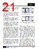
23 / 51 page  IR3447 23 www.irf.com © 2013 International Rectifier July 17, 2013 Users can configure the IR3447 to use a single supply or dual supplies. Depending on the configuration used the PVin, Vin and VCC pins are connected differently. Below several configurations are shown. In an internally biased configuration, the LDO draws from the Vin pin and provides a gate drive voltage, as shown in Figure 15. By connecting Vin and PVin together as shown in the Figure 16, IR3447 is an internally biased single supply configuration that runs off a single supply. IR3447 can also use an external bias to provide gate drive voltage for the drivers instead of the internal LDO. To use an external bias, connected Vin and VCC to the external bias. PVin can use a separate rail as shown in Figure 17 or run off the same rail as Vin and VCC. Figure 15: Internally Biased Configuration Figure 16: Internally Biased Single Supply Configuration Figure 17: Externally Biased Configuration When the Vin voltage is below 6.8V, the internal LDO enters the dropout mode at medium and heavy load. The dropout voltage increases with the switching frequency. Figure 18 shows the LDO voltage for 600kHz and 1000kHz switching frequency. Figure 18: LDO_Out Voltage in dropout mode CBYP This pin reflects the internal reference voltage which is used by the error amplifier to set the output voltage. In most operating conditions this pin is only connected to an external bypass capacitor and it is left floating. A minimum 100pF ceramic capacitor is required from stability point of view POWER GOOD OUTPUT IR3447 continually monitors the output voltage via the sense pin (Vsns) voltage. The Vsns voltage is an input to the window comparator with upper and lower threshold of OVP(trip) and VPG_high(lower) |
|
Link URL |
| Does ALLDATASHEET help your business so far? [ DONATE ] |
About Alldatasheet | Advertisement | Contact us | Privacy Policy | Link to Datasheet | Link Exchange | Manufacturer List All Rights Reserved©Alldatasheet.com |
| Russian : Alldatasheetru.com | Korean : Alldatasheet.co.kr | Spanish : Alldatasheet.es | French : Alldatasheet.fr | Italian : Alldatasheetit.com Portuguese : Alldatasheetpt.com | Polish : Alldatasheet.pl | Vietnamese : Alldatasheet.vn Indian : Alldatasheet.in | Mexican : Alldatasheet.com.mx | British : Alldatasheet.co.uk | New Zealand : Alldatasheet.co.nz |
|
Family Site : ic2ic.com |
icmetro.com |
 British ▼
 English
 Chinese
 German
 Japanese
 Russian
 Korean
 Spanish
 French
 Italian
 Portuguese
 Polish
 Vietnamese
 Indian
 Mexican
 British
 New Zealand